Injection Molding Project - Axolotl Boat
Project Summary
Designed and manufactured a multi-part injection molded toy featuring an axolotl riding a boat, created for ME 340-2 manufacturing processes course.
Completed for ME 340-2 at Northwestern University, our team of three (Cole Abbott, Matthew Martinez, Xing Yu Chen) designed and produced an axolotl riding a boat toy using injection molding techniques. The final assembly features an axolotl with removable gills freely riding atop a boat made from two symmetrical halves. I was responsible for designing the boat component in NX CAD, creating the complete mold design (core and cavity), programming the CNC toolpaths in NX CAM, machining the boat molds on Haas CNC machines, and performing manual machining operations. My teammates handled the axolotl and gill design and fabrication.
CAD Models
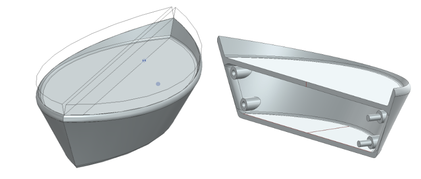
Boat half CAD model designed in NX
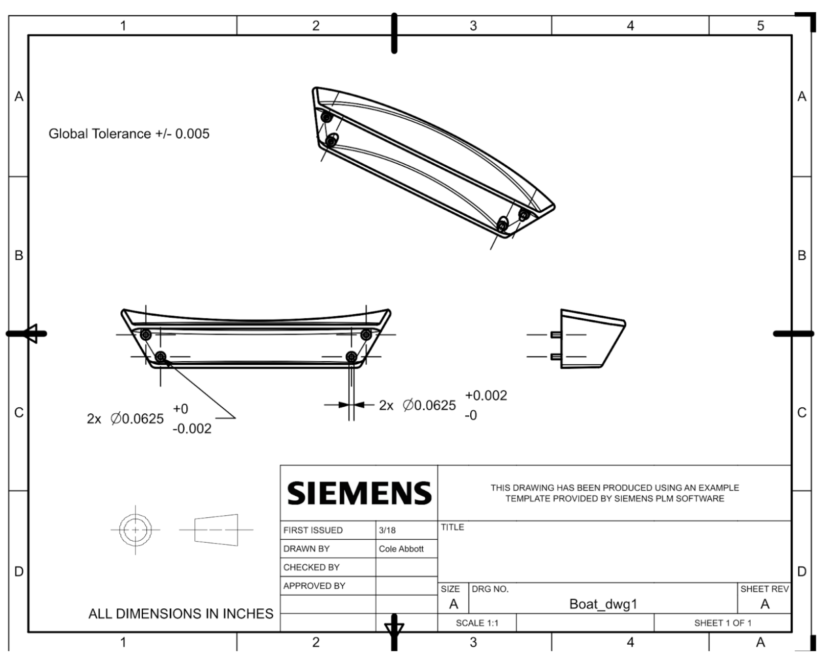
Technical drawing with dimensions
Boat Design for Injection Molding
The boat was designed with a uniform wall thickness of 0.05" to ensure consistent material flow and minimize warping. Key design considerations included:
- Draft Angles: All vertical surfaces include draft angles to facilitate part ejection from the mold
- Wall Thickness: Started at 0.05" uniform thickness, increasing to 0.0845" due to opposing draft angles required by the boat geometry
- Symmetrical Design: The boat was split into two identical halves, allowing for simpler mold design and the ability to create larger assemblies
- Interference Fit Assembly: Holes designed with 0.0625" diameter for press-fit pins with 0.0025" interference at 30 MPa design stress
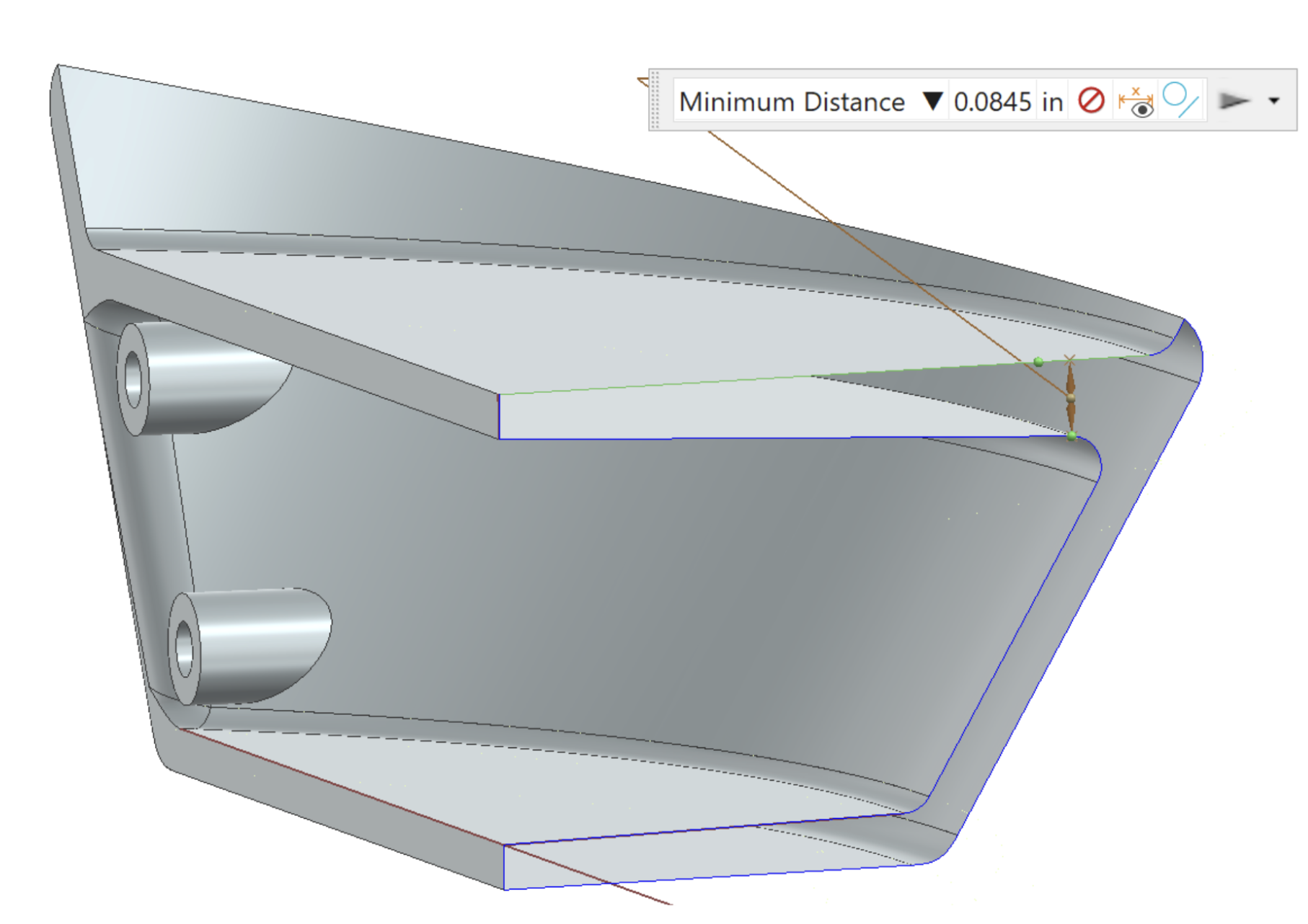
Cross-section showing wall thickness and draft angles
Mold Design & Strategy
The boat mold used a standard core/cavity design, but presented a unique challenge: the required geometry would have created a deep slot that was not machinable with our available tooling and CNC machines. To solve this, I designed the mold to be split into two separate parts that would be bolted together during molding.
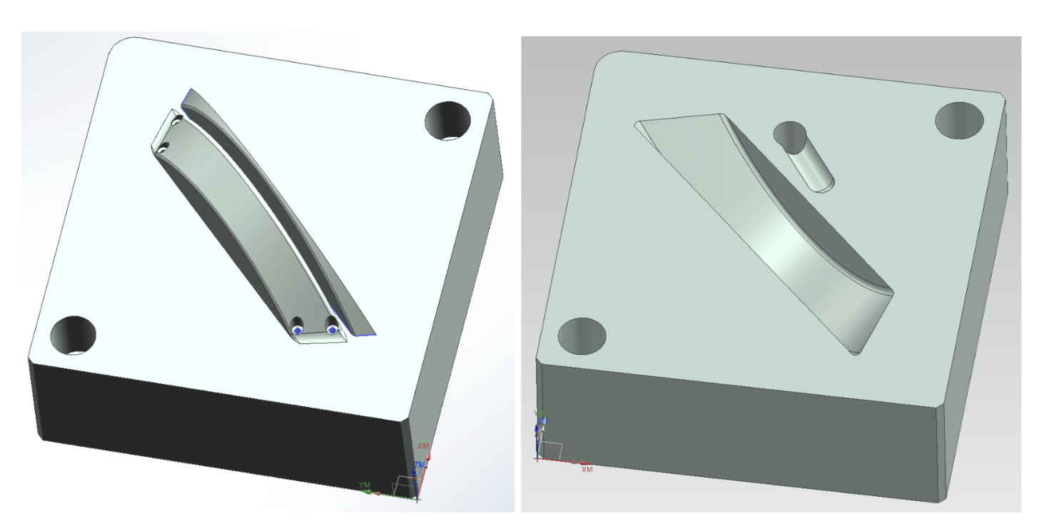
Mold core and cavity CAD models
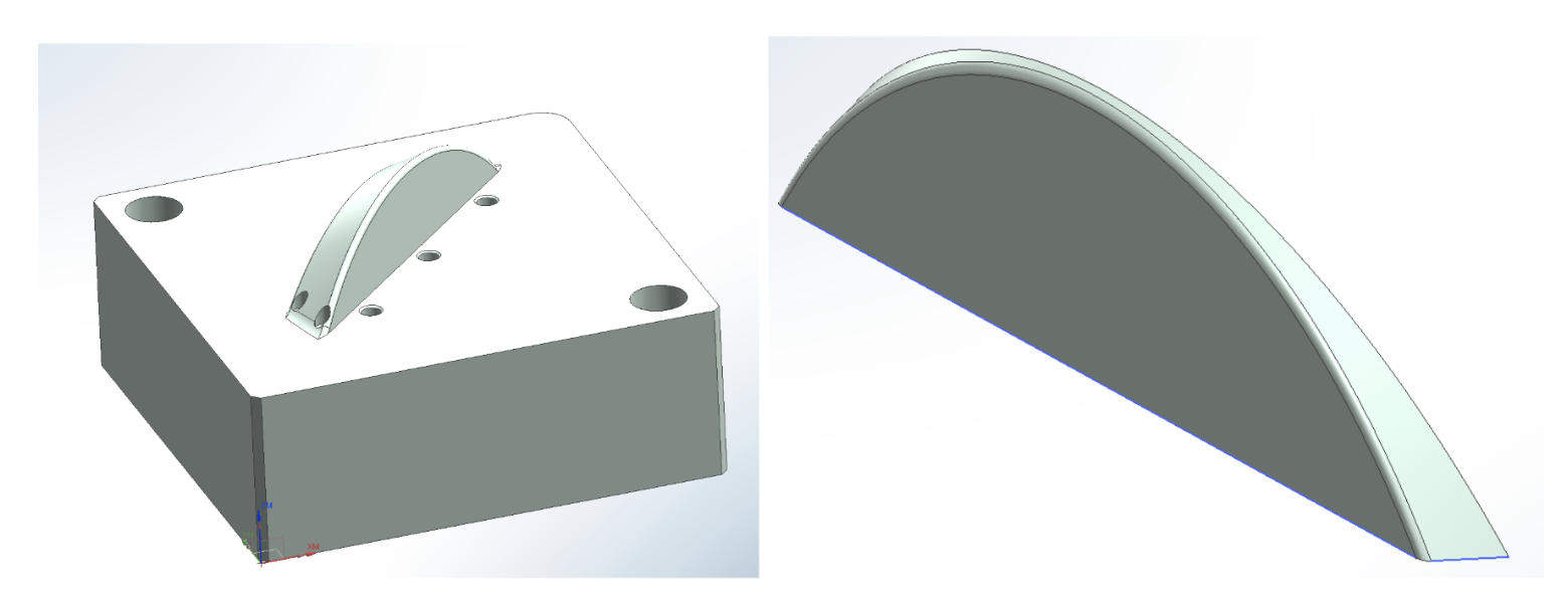
Detailed view of mold assembly
One part was CNC machined using the NX CAM program I developed, while the other was made on a manual mill since its geometry was simple. A custom fixture plate was designed and machined to securely hold the mold insert during manual machining operations.
CNC Machining Process
Using NX CAM, I programmed multi-axis toolpaths for the Haas CNC machines in the Ford machine shop. The machining strategy included:
- Roughing operations with larger tools (0.375" ball mill) to remove bulk material quickly
- Finishing passes with smaller tools (0.125" and 0.25" ball mills) for precision and surface finish
- Planar milling for runner geometry
- Cavity milling operations for detailed features
- Post-machining light sanding to remove machine marks and ensure smooth part release
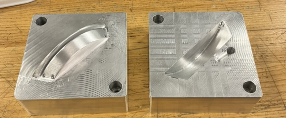
Both mold halves after CNC machining
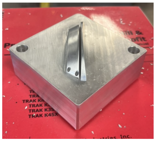
Finished mold ready for injection molding
Injection Molding Parameters
After machining and assembly, the boat molds were used to injection mold parts from polypropylene. Through iterative testing, we optimized the molding parameters:
- Temperature: 450°C
- Injection Time: 6 seconds
- Cooling Time: 20 seconds
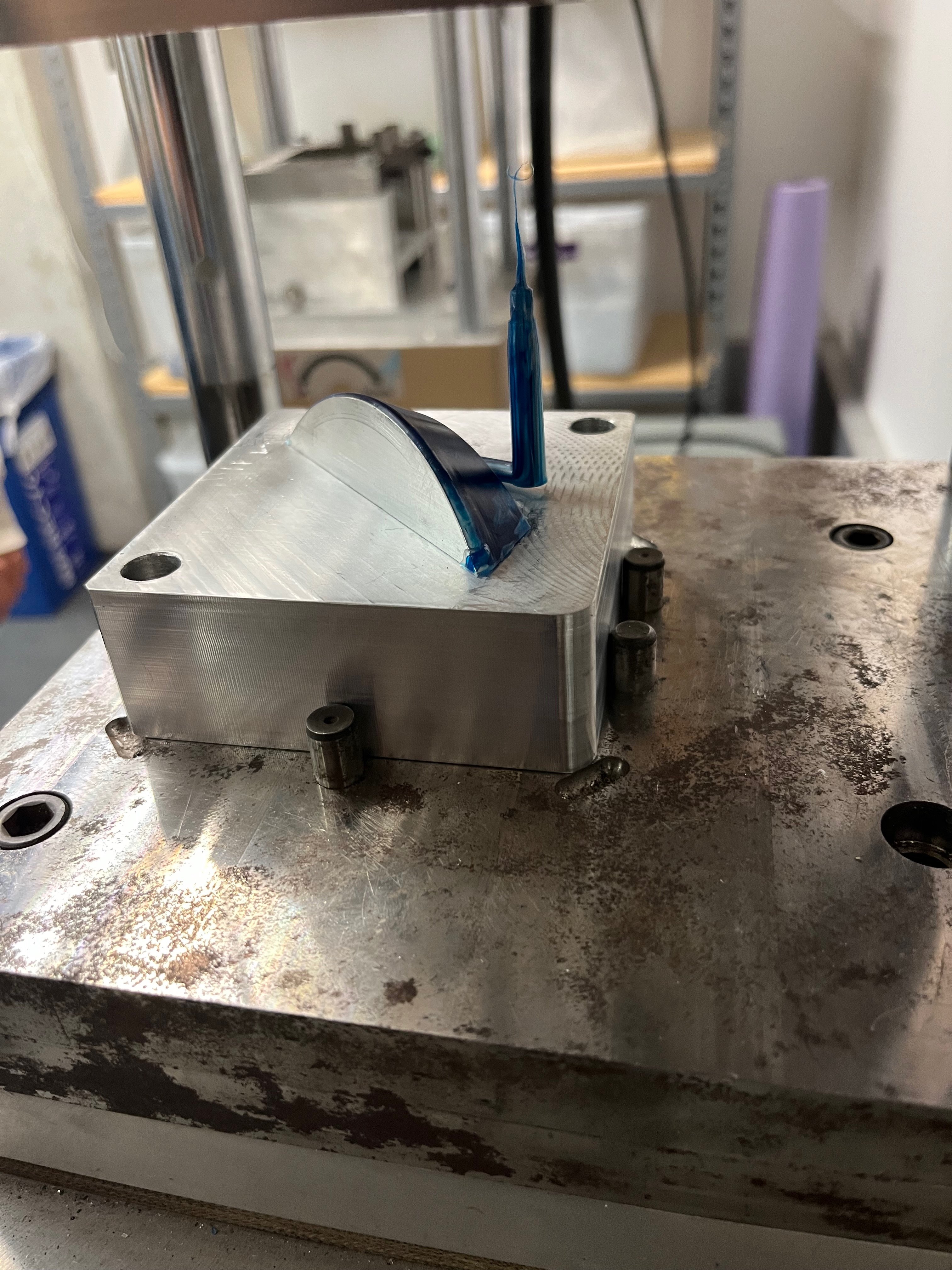
We started with conservative parameters (20-second injection, 30-second cooling) and gradually reduced them until defects like short shots began to appear, then backed off to ensure quality. The draft angles and smooth surface finish allowed for easy part removal from the mold.
Mold installed in the injection molding machine
Final Parts
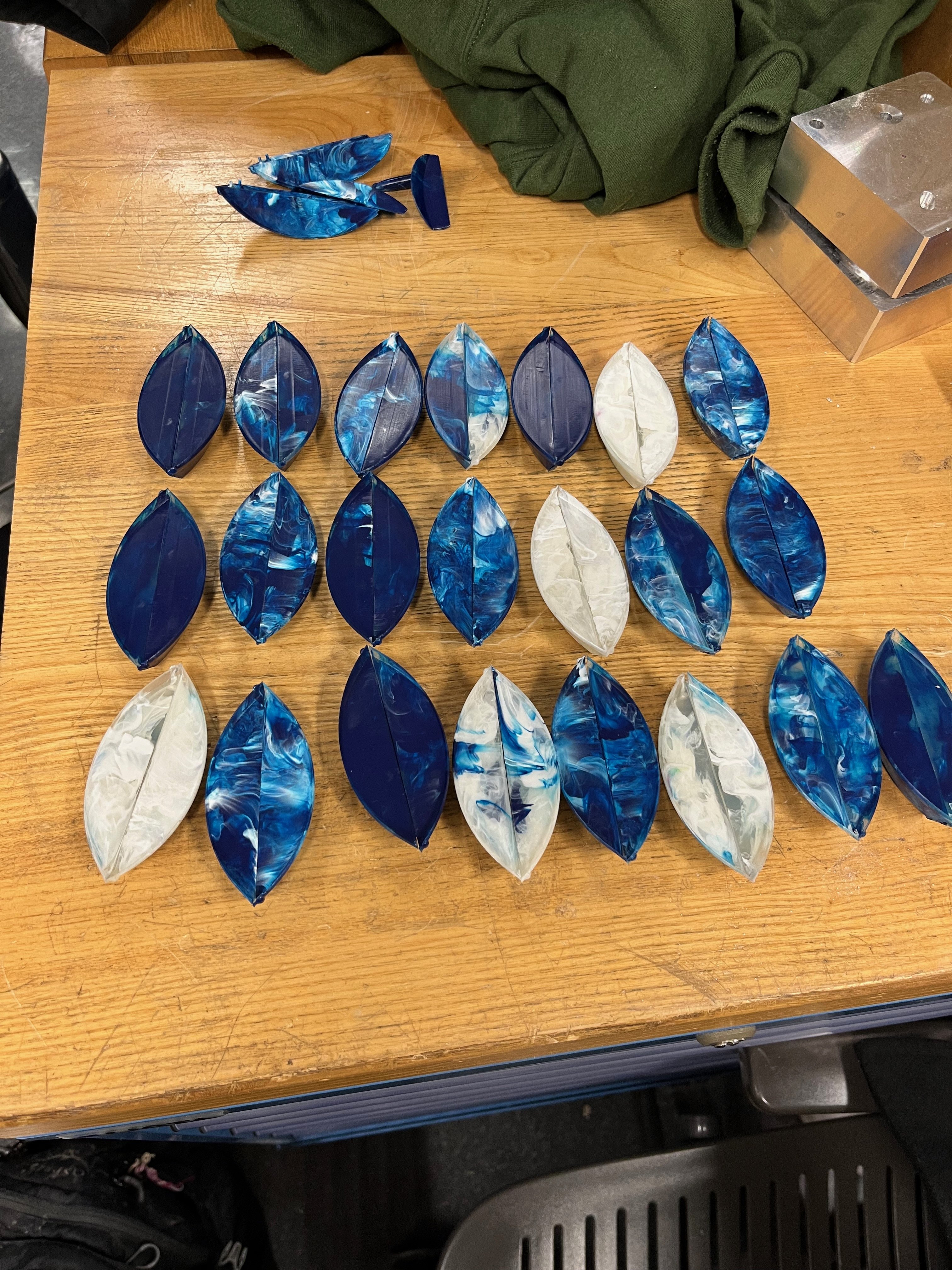
Multiple boat halves successfully molded
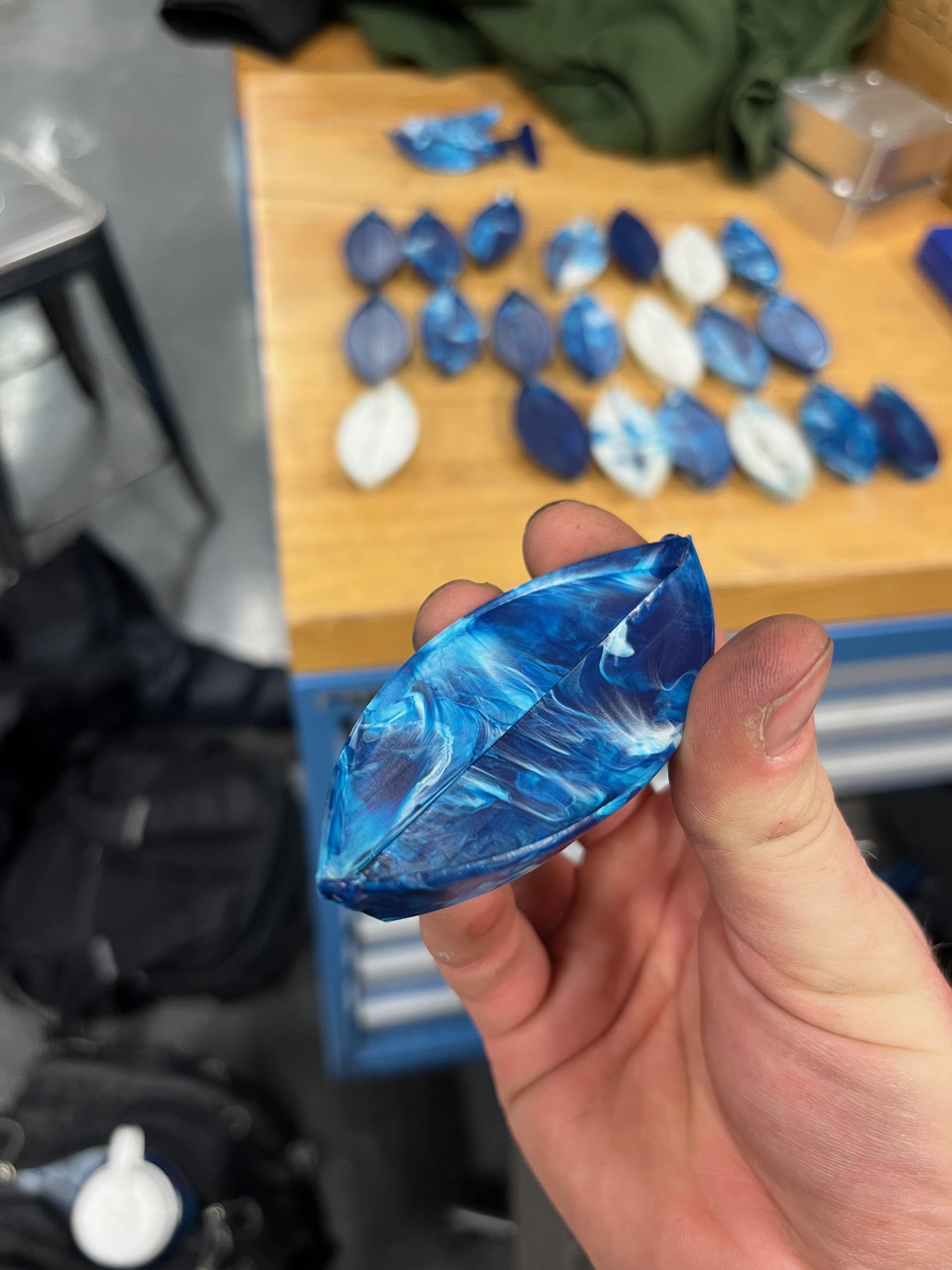
Assembled boat showing press-fit connection
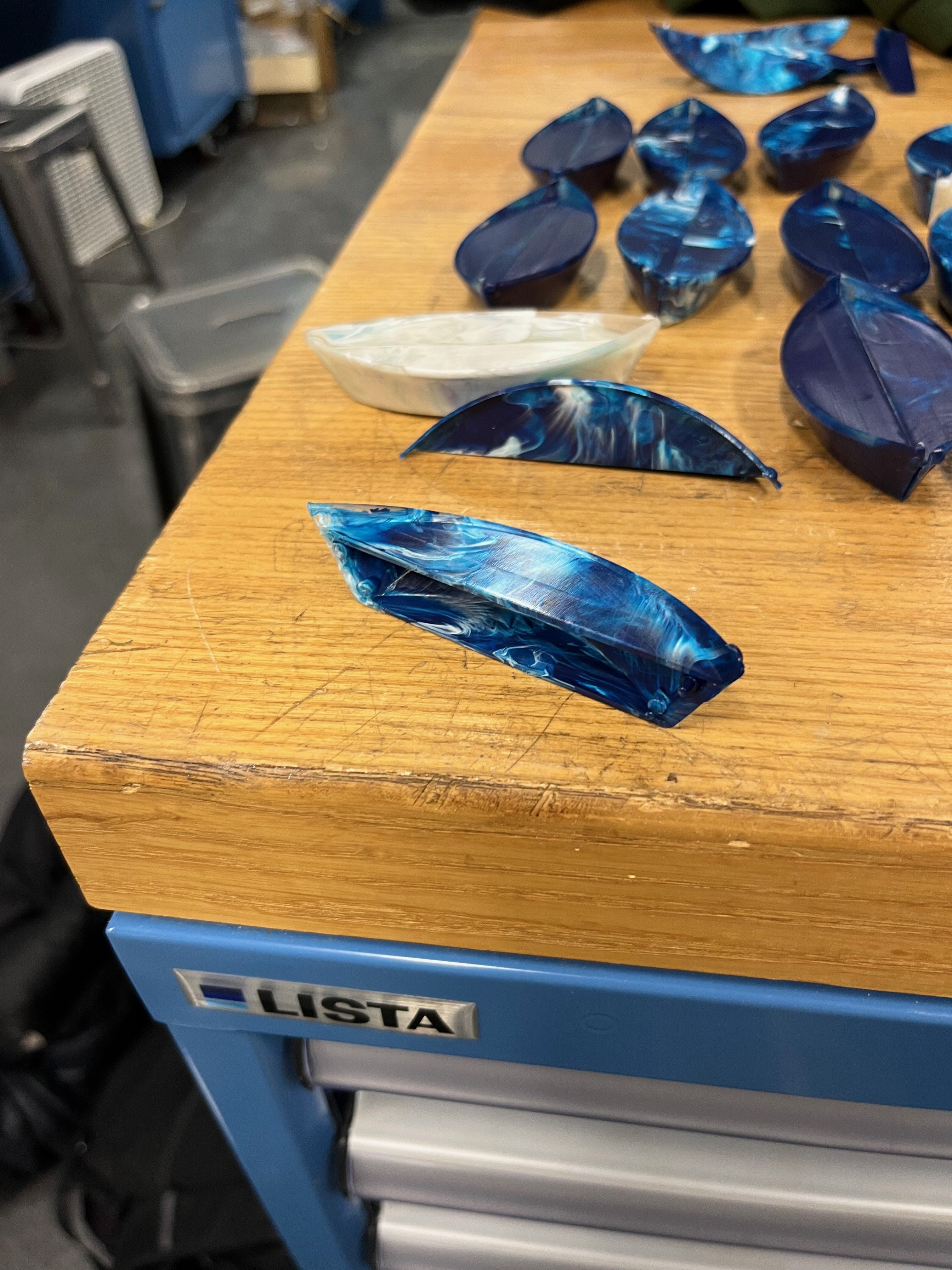
Boat half showing detail and surface finish quality
Quality Control & Metrology
We conducted a metrology study on the boat's bottom thickness to validate dimensional accuracy. Results showed:
- Molded parts were very accurate to the CAD design
- Only a few parts fell more than 0.005" off the intended size
- Parts tended to be slightly smaller than designed due to polypropylene shrinkage (expected behavior)
- Two identical boat halves press-fit together easily and securely to form the complete boat
Challenges & Solutions
Several technical challenges were encountered and resolved during the project:
- Deep Slot Machining: The required mold geometry created non-machinable deep slots with our tooling. Solved by splitting the mold into two parts - one CNC machined, one manually machined, then bolted together
- Tool Changer Issue: During cavity machining, the tool changer didn't properly grab the tool, resulting in a small gouge. Identified early and did not impact the final molded parts
- Collet Tightness: A collet wasn't held tight enough, drilling a small divot in the boat cavity. Caught early with minimal impact on final parts
- Surface Finish: Light sanding was required post-CNC to remove machine marks that would transfer to molded parts
Key Learning Outcomes
This project provided comprehensive hands-on experience in the complete injection molding workflow:
- Designing parts specifically for injection molding (draft angles, wall thickness, parting lines)
- Creating mold designs that account for manufacturing constraints and available tooling
- Developing CNC programs using NX CAM for complex 3D mold cavities
- Operating Haas CNC machines and troubleshooting machining issues
- Manual machining techniques for fixture plates and mold components
- Optimizing injection molding parameters through iterative testing
- Understanding material behavior (polypropylene shrinkage, flow characteristics)
- Conducting dimensional metrology and statistical process control
- Team collaboration and division of labor in a manufacturing project