
Electronic CVT System
Project Summary
Designed and built an electronic continuously variable transmission (eCVT) for a Baja SAE off-road vehicle, implementing position sensing, motor control, and PID-based actuation.
What is an eCVT?
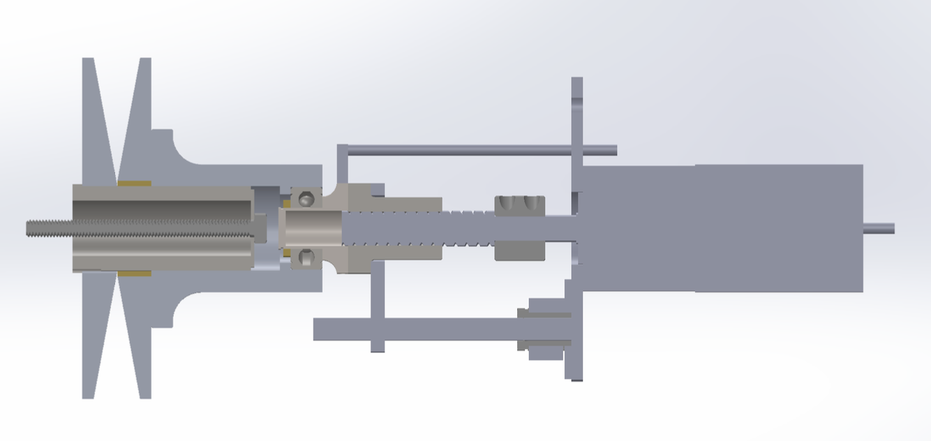
A continuously variable transmission (CVT) uses two sets of sheaves (conical metal pieces) connected by a cogged V-belt that slide together or apart to create different gear ratios. In our electronic CVT, this motion is created by a motor that spins a lead screw, which translates rotational motion into linear axial motion.
One sheave (the primary) is actuated along the axis of the engine shaft while the other (the secondary) remains fixed. The secondary sheave responds to changing pressure with a spring that allows it to expand or contract. We use a linear bearing and post for stability and smooth sliding motion.
Primary Sheave Cross Section
System Architecture
We read the RPM of the engine using magnets embedded in the back of the stationary primary sheave with a latching hall sensor. Both the RPM and the position of the moving primary sheave are fed into the ESP32 microcontroller, which runs a PID control loop to move the motor (and thus the sheave) to the desired position.

Motor Selection
The motor is the most critical component, as it must provide sufficient side force to hold the belt in place without slipping. We required a minimum of 3Nm torque with 150+ RPM speed (to move the sheaves fully in 1 second).
After exploring planetary geared brushless DC motors, stepper motors, and hybrid steppers, we settled on a geared brushless DC motor that met our criteria: reasonable weight, 24V operation, acceptable current draw, and sufficient torque/speed specifications.
The motor is driven by a BLD-510B motor driver that translates the microcontroller's PWM signals into the three-phase signals needed for BLDC operation. This motor driver was not the best choice, because it does not support FOC, meaning it is hard to get smooth low-speed operation, and struggles to change direction. However, it was very affordable and works well enough for our application.
Custom Control Board
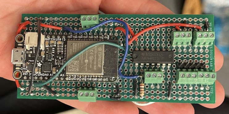
A solderable breadboard integrates the ESP32 microcontroller, motor driver connections, sensor inputs, and power regulation circuitry into a compact package designed for the harsh environment of off-road racing.
Position Sensing
We use a combination approach for position sensing: a linear potentiometer reads the initial position on startup, then the motor's built-in encoder tracks position during operation. This approach minimizes noise issues that would arise from relying solely on a potentiometer mounted on a vibrating vehicle, and avoids the need for a startup homing routine.
Power System
The system runs on 24V using two 12V LiFePO4 batteries connected in series. With a motor rated current of 7A and additional electronics drawing ~0.2A, we sized the batteries for 40Ah capacity to ensure reliable operation throughout a 4-hour endurance race.
A buck converter steps down the 24V to the 5V needed by the ESP32 and hall sensors, chosen for its efficiency and minimal heat dissipation compared to linear regulators.
Electronics Housing
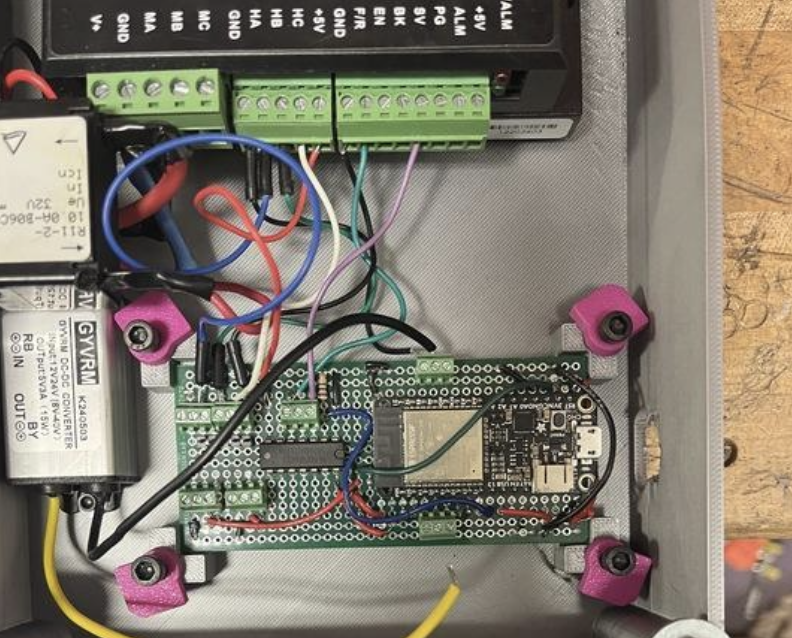
The electronics are housed in a waterproof enclosure mounted behind the wings above the splash guard, protecting them from mud, water, and debris encountered during off-road racing.
Testing & Validation
Extensive testing was performed on a bench setup before vehicle integration. Each component and code section was validated individually, then as a complete system.
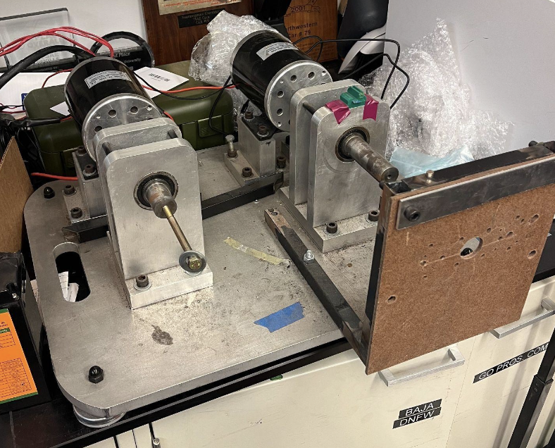
Bench test setup for component validation
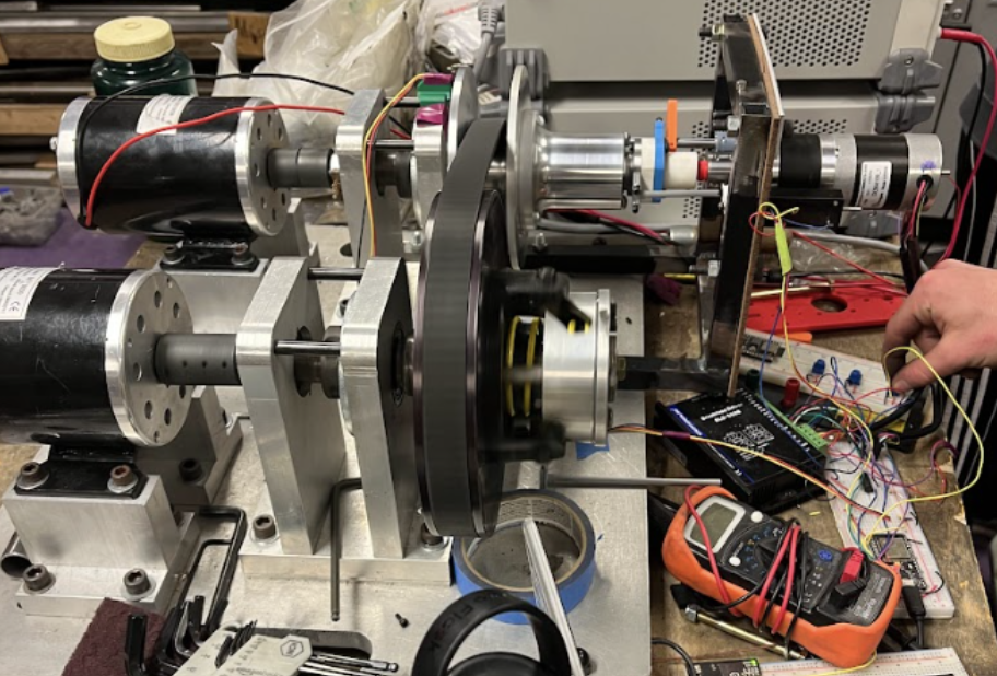
System under test with simulated loads