QuackTrack Robot
Project Summary
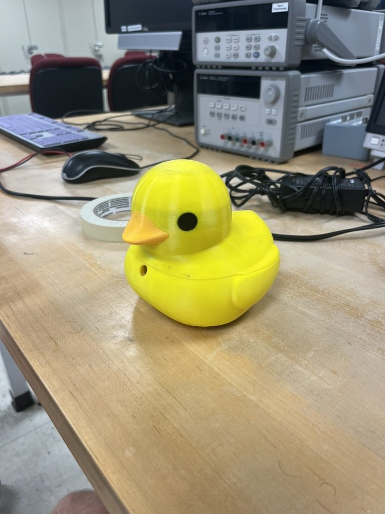
Designed and built a robotic duck toy that autonomously detects and follows a person using computer vision, WebSocket communication, and real-time PID motor control with an IMU for smooth and responsive motion.
This project was completed for EE327: Electronic System Design II at Northwestern University. The goal was to create an interactive robotic toy that could autonomously follow a person using computer vision and embedded control systems.
System Architecture
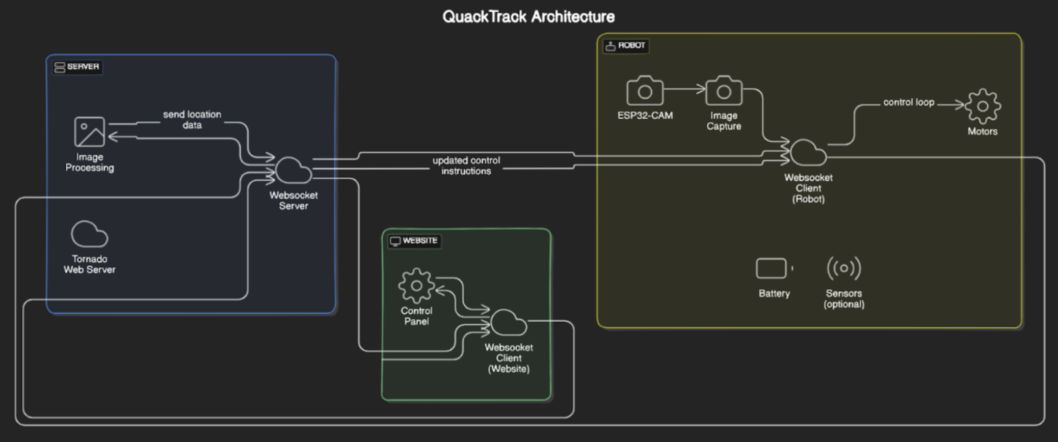
The QuackTrack robot uses a distributed architecture that separates image processing from motor control. The ESP32-CAM microcontroller captures images and handles motor control, while a Python server running on a computer performs the computationally intensive computer vision processing.
Communication Flow
- ESP32-CAM captures images and sends them to the server over WebSocket
- Server processes images using YOLO object detection to identify and locate people
- Server sends target coordinates back to the ESP32-CAM
- ESP32-CAM adjusts motor speeds to follow the target using PID control
Hardware Components
The robot is built around several key hardware components that work together to enable autonomous following behavior:
- ESP32-CAM: Dual-core microcontroller with integrated camera for image capture and wireless communication
- MPU-6050 IMU: 6-axis inertial measurement unit for measuring angular velocity and implementing precise rotation control
- Micro Metal Gear Motors: Two high-torque motors with different gear ratios for differential drive locomotion
- 3.7V LiPo Battery: Rechargeable power source for portable operation
Hardware Internals
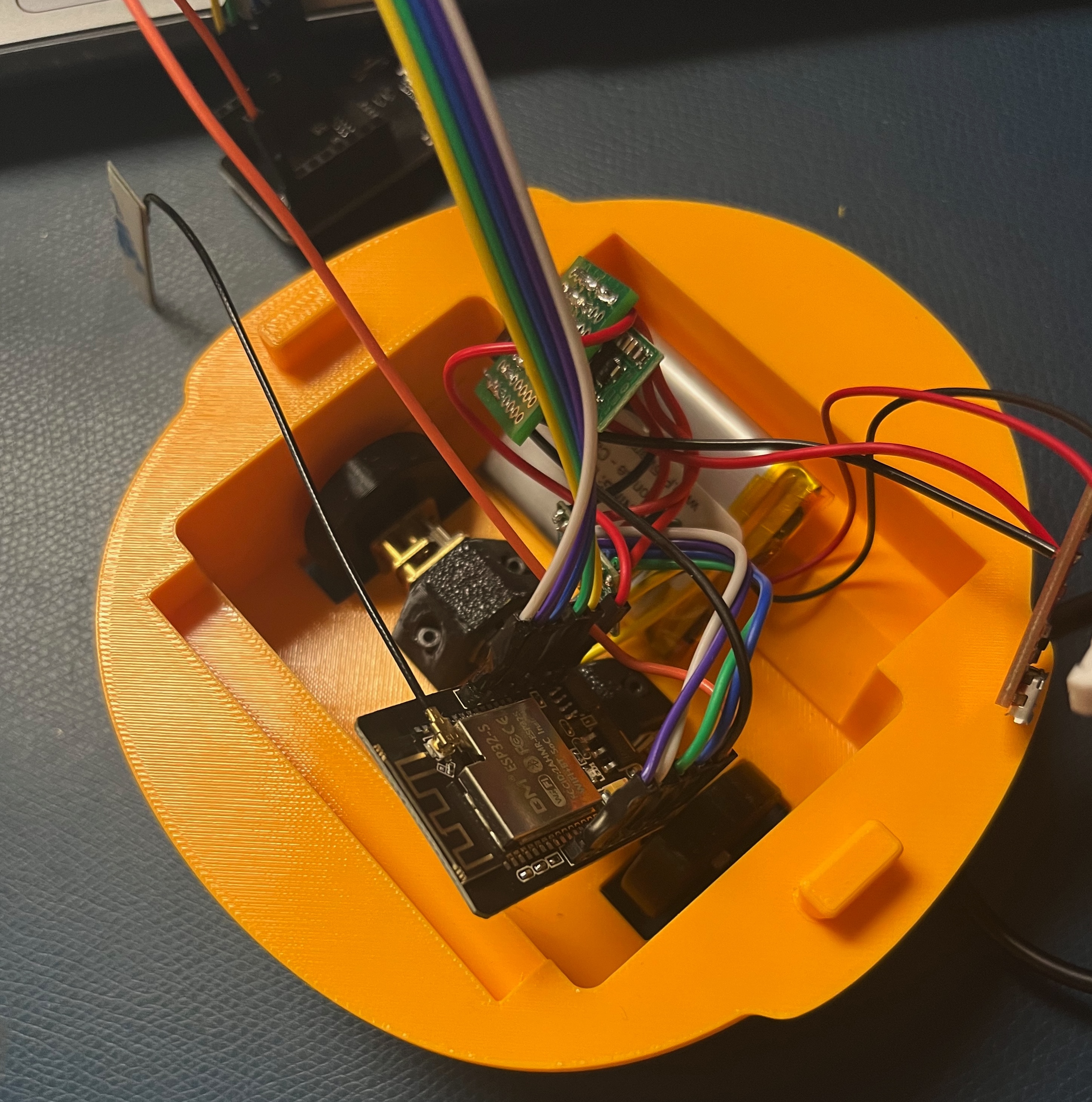
Inside view showing the ESP32-CAM module, motor connections, IMU sensor, and battery placement. The compact design integrates all electronics within the duck chassis.
Computer Vision Processing
The Python server uses OpenCV and the YOLOv3 deep learning model for real-time person detection. When a person is detected in the image, the system calculates the center position of all detected people and sends the averaged coordinates back to the robot.
The server processes images with a confidence threshold of 0.5, filtering for class ID 0 (person). When multiple people are detected, their positions are averaged to determine the primary tracking target. The processed image with bounding boxes and tracking indicators is sent back to a web interface for visualization.
Dual PID Control System
The robot implements a cascaded control architecture with two PID loops working in tandem:
Camera PID Controller
The outer loop uses target position from the camera to calculate desired angular velocity and forward speed:
- Maintains the target centered in the camera's field of view (setpoint: x=160 pixels)
- Adjusts forward speed based on target distance (y-axis position)
- Updates only when new camera data is received
IMU PID Controller
The inner loop reads gyroscope data and controls motor speeds to achieve the desired angular velocity:
- Runs at 200 Hz (5ms intervals) for responsive control
- Uses z-axis gyroscope readings to measure actual angular velocity
- Applies differential drive: left and right motors receive opposite turning commands plus forward speed
- Tuned PID gains (Kp=350, Ki=15) provide stable tracking with minimal oscillation
Firmware Architecture
The ESP32 firmware is built using FreeRTOS tasks for concurrent operation. The camera PID and IMU control loops run on separate tasks pinned to core 1, allowing them to execute independently without blocking WebSocket communication.
The modular code structure separates concerns: camera.cpp handles image capture, myWebsocket.cpp manages network communication, control.cpp implements the PID algorithms, and motor.h provides a simple interface for motor control with PWM and direction management.
Operating Modes
The robot supports two operating modes that can be toggled remotely:
- Manual Mode: Direct motor control via web interface commands
- Autonomous Mode: Camera-based PID control for person following
When no person is detected in autonomous mode, the robot gradually reduces its turning rate to 80% to continue searching for the target while maintaining smoother motion.
Challenges & Solutions
Several technical challenges were overcome during development:
- Clock Interference: The camera clock caused interference with the wifi, which ment that the wifi and camera would work independently, but when running together performance was signficantly impacted. To fix this we lowered the clock signal of the camera.
- Real-time Performance: FreeRTOS tasks enabled concurrent execution of control loops and network communication
- Network Latency: The cascaded PID approach allows the inner IMU loop to maintain smooth control even when camera updates are delayed
Results
The robot successfully demonstrated autonomous person-following behavior with smooth tracking and responsive turns. The dual PID control system effectively compensated for motor asymmetries and provided stable tracking despite network latency. The project showcased effective integration of embedded systems, computer vision, and control theory to create an engaging interactive robot.