Northwestern University Research Project
Acoustic E-Skin Research
Project Summary
Developed PIC32 firmware for an acoustic electronic skin, then continued the project through PCB bring-up, transducer testing, and 3D-printer-based force experiments to evaluate touch localization from reflected waves.
The system uses piezoelectric transducers to send acoustic pulses through a soft SimuGel skin, then samples the returning waveform fast enough to estimate where a force changed the wave path. My work started with the embedded acquisition firmware in Spring 2025, then continued into PCB bring-up, data collection software, and the experiments needed to learn whether the sensor could produce usable touch-location data.
Firmware start
Spring 2025
Initial PIC32 acquisition firmware built in MPLAB Harmony.
ADC throughput
6.25 Msps
12-bit samples streamed from the PIC32 through DMA and USB.
Small-array edge
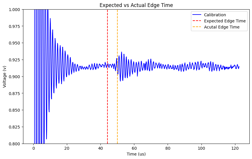
~50 us
Measured return on a 32 mm skin, close to the 44.17 us prediction.
Spring 2025: Firmware Foundation
The first phase of the project was writing the PIC32 firmware that made acoustic data collection possible. The goal was to reliably capture a short, high-speed ADC window after each transducer pulse and send that waveform to a computer for analysis.
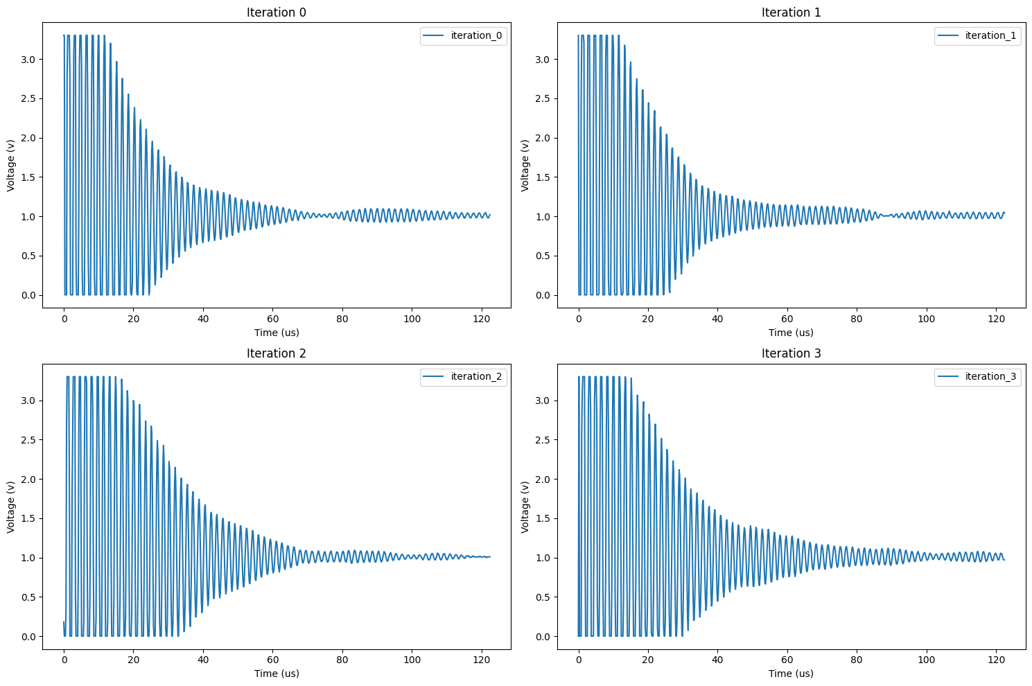
- Configured the PIC32 MZ EF ADC to sample 12-bit waveform data at 6.25 Msps.
- Used DMA so ADC samples could move into RAM without blocking the processor during each pulse capture.
- Built a USB vendor-device data path for streaming captured buffers to a PC for visualization and processing.
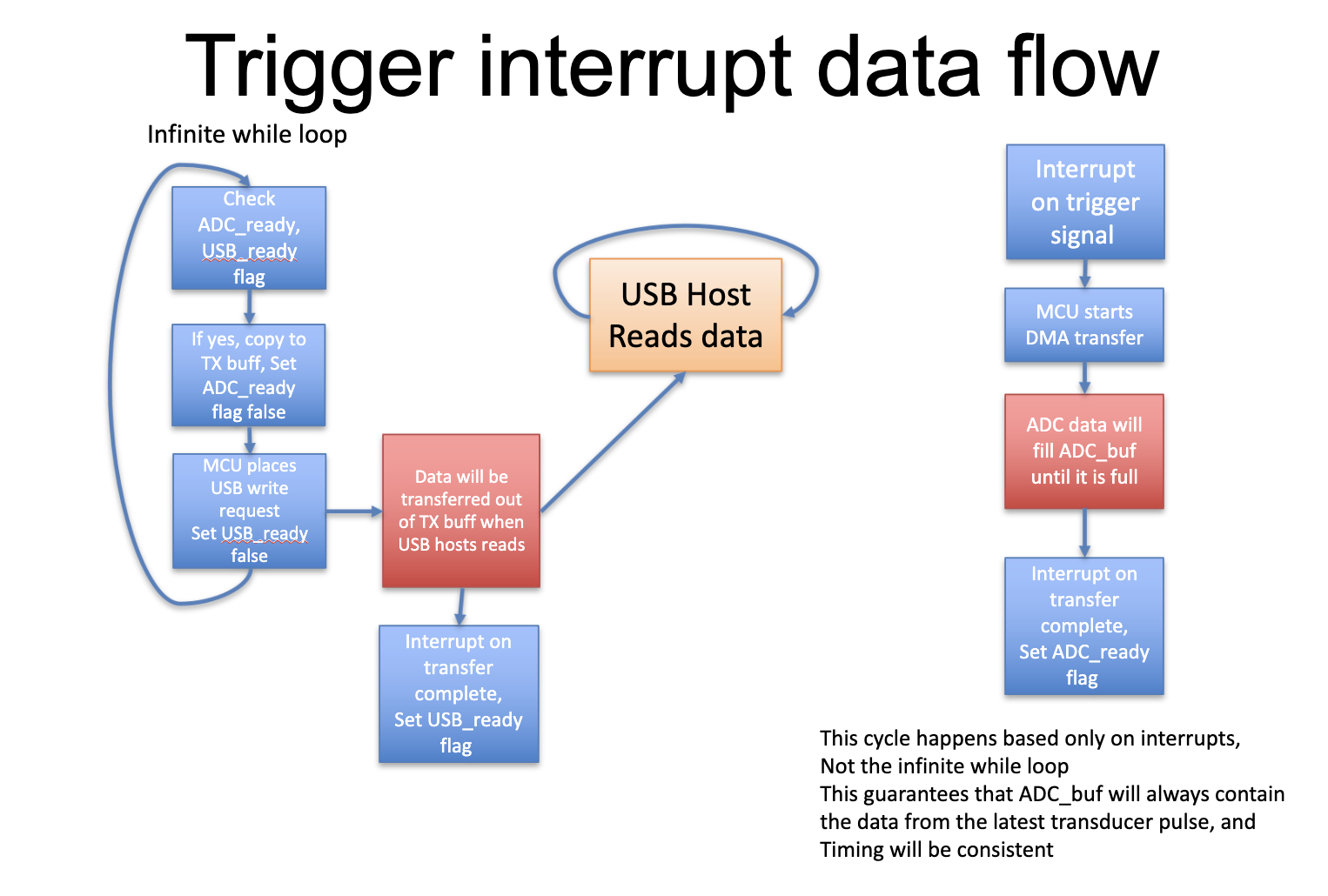
- Structured the firmware around trigger and transfer-complete interrupts so timing stayed consistent from pulse to pulse.

Winter 2026: Hardware Bring-Up
The next phase was debugging the PCB board. The board initially had broken USB, PIC crashes, and enough analog interference to corrupt the ADC path.
- Restored USB by replacing the PCB's 26 MHz crystal with a 12 MHz oscillator compatible with the PIC32 USB peripheral.
- Diagnosed PIC crashes caused by negative voltage pulses and high-voltage pulser interference coupling into the ADC input.
- Validated a series-resistor fix and bypassed the noisy ADCIN trace so four transducer channels could stream reliably over USB.
Spring 2026: Transducer Testing
With the collection pipeline working, the spring work shifted toward repeatable experiments. We integrated the sensor with a 3D-printer-based tactile testbed that moves a load-cell probe to controlled positions, then compared different transducer arrays and skin sizes.
The data showed progress, but also clarified the core limitation: reflections from the edge of the skin were detectable, while reflections from a local press were small, setup-sensitive, and not reliable enough for a polished touch-location demo.
Transducer Tradeoffs
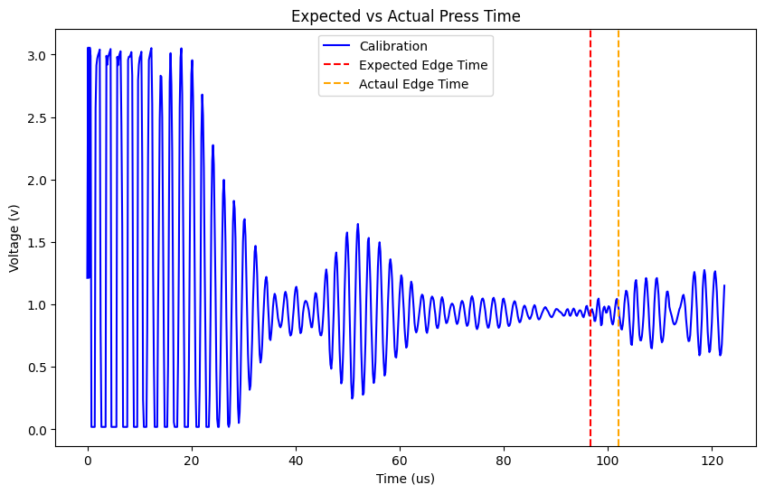
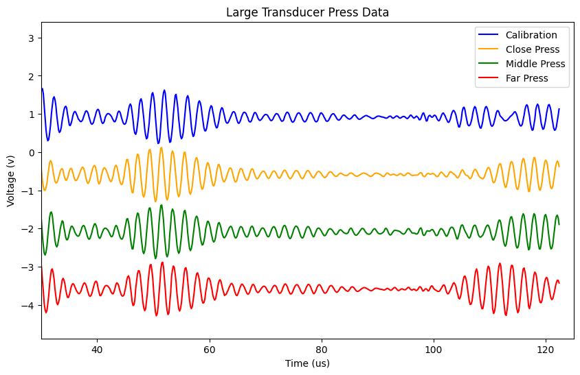
Testing larger transducers revealed a useful design tradeoff. They received a much stronger reflected edge signal, but also rang for about 30 us after excitation, creating a roughly 25 mm region where reflected waves could not be cleanly interpreted.
Small transducers
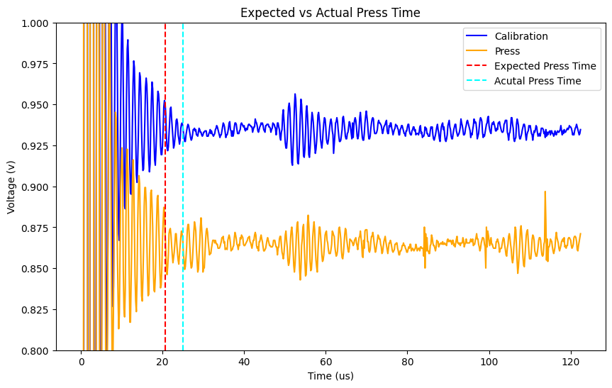
The 32 mm skin showed a detectable edge reflection near 50 us and a probe press near 25 us, but the reflected signal was only about 0.05 V after 50x receiver amplification.
Large transducers
The larger receiver produced a much stronger edge return on a 70 mm skin, but its roughly 30 us ringing period created a dead zone and made direct press reflections harder to isolate.
System direction
The most promising next experiment is to separate the transmitter and receiver so a small transducer can emit a sharp pulse while a larger transducer records the response.
PCB & Firmware Updates
The spring PCB revision separated control signals, reduced interference around the analog path, and added a synchronization signal between the Arduino multiplexer controller and the PIC32 data collector. The PIC can use that sync pulse to reset its channel counter and tag USB packets with the correct transducer channel.
The new board still needed input current limiting to prevent crashes from negative receiver output. A future revision should constrain the receiver output directly to the PIC's 0-3.3 V ADC range, likely with a rail-to-rail amplifier stage instead of relying on a bias tee to shift the signal.
Outcome
By the end of spring, the hardware, PIC firmware, Arduino synchronization, and Python collection software were reliable enough to support structured experiments across multiple transducer arrays. The research did not reach a full demo, but it identified the limiting physics and hardware choices: the transducer-skin interface, receiver dynamic range, and the need for a cleaner transmit/receive architecture.